


► Advanced laboratory electrical calibrator / Dual input thermometer
► CALYS 1500, most advanced and accurate laboratory electrical
calibrator of the range, does not only work as a simulator (IN / OUT)
but also as a dual channel thermometer (IN / IN) to perform comparison
calibration.
► It calibrates HART transmitters (HART communicator) and thermistors.
※ For industry and laboratory application only
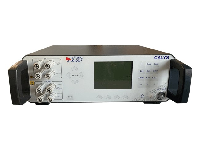
CALYS 1500, most advanced and accurate laboratory electrical calibrator of the range, does not only work as a simulator (IN / OUT) but also as a dual channel thermometer (IN / IN) to perform comparison calibration. It calibrates HART transmitters (HART communicator) and thermistors. It is the perfect tool for advanced process maintenance and use on test bench in all industries. Suitable for all field and lab measurements, it can simultaneously measure and generate over two isolated channels various signals of temperature, resistance, process, pressure and frequency in one single instrument. Providing extended functionalities (temperature simulation, scaling, steps, synthesizer, statistical functions…) and audit trails, CALYS 150 complies with both 21 CFR Part 11 and NADCAP Heat Treatment standards and makes advanced data exploitation and full data traceability easier. 10 full configurations can be saved and recalled by the user or the user group, making CALYS 1500 the ideal tool for regular and repeated tasks. High performances in measurement and simulation for CALYS 1500:
Temperature Up to 0.005 % RDG
Resistance Up to 0.006 % RDG and 50 KΩ range
Current: Up to 0.007 % RDG and 100 mA range + Loop Supply 24 V
Voltage: Up to 0.005 % RDG and 50 V range
Frequency: Up to 0.01 % RDG and 100 KHz range
Pressure: With an external pressure module (comparison calibration with a pressure pump)
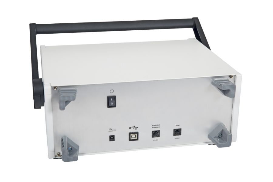
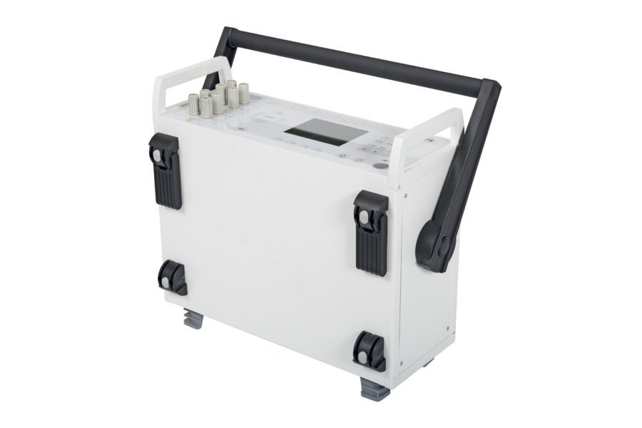
Innovative and ergonomic designMetal housing for enhanced robustnessCapacitive touch panelUSB communicationCarrying handleBattery and main powered |
|

Calibration procedures and DATACAL software
Using this user-friendly instrument, calibration tasks can be quickly carried out over the whole process chain. Take the documenting process calibrator to the field with you during the whole week with 10 calibration procedures stored in the device. Run the procedure after connecting the probes to the instrument and save the results for onsite easy and quick calibration. Back to the office, you can then upload the data on a computer in order to issue customized calibration certificates with dedicated calibration software DATACAL.
Graphic screen and display resolution
CALYS 1500 allows the digit number after the dot to be selected: This function is justified by the needs of users who want or not to display the best resolution for calibration or on the contrary limit it for simple verifications. CALYS 1500 dual display indicates permanently the measurement value, and also the emitted value, the gauge and the used functions. On the top date, time and also external temperature are also indicated. During measuring average, maximum, minimum and the number of measurements are displayed on the left. While for emission this part of screen displays all details of ramps, steps and constant value emission functions. Drop-down menus are used with the navigator, and an on-line help is available to make easier connections of probes and wires.
Specifications and performances in temperature @23°C ±5°C
Uncertainty is given in % of reading (CALYS 1500 display) + fixed value.
Resistive probes: Measurement and simulation
| Sensor | Range (Input and Output) | Resolution | Accuracy / 1 year (Measurement) | Accuracy / 1 year (Simulation) |
| Pt50 (α = 3851) | -220°C to +850°C | 0.01°C | 0.006% RDG + 0.04°C | 0.006% RDG + 0.04°C |
| Pt100 (α = 3851) | -220°C to +850°C | 0.01°C | 0.006% RDG + 0.03°C | 0.006% RDG + 0.035°C |
| Pt100 (α = 3916) | -200°C to +510°C | 0.01°C | 0.006% RDG + 0.03°C | 0.006% RDG + 0.035°C |
| Pt100 (α = 3926) | -210°C to +850°C | 0.01°C | 0.006% RDG + 0.03°C | 0.006% RDG + 0.035°C |
| Pt200 (α = 3851) | -220°C to +850°C | 0.01°C | 0.006% RDG + 0.04°C | 0.006% RDG + 0.04°C |
| Pt500 (α = 3851) | -220°C to +850°C | 0.01°C | 0.006% RDG + 0.03°C | 0.006% RDG + 0.04°C |
| Pt1000 (α = 3851) | -220°C to +740°C | 0.01°C | 0.006% RDG + 0.03°C | 0.006% RDG + 0.035°C |
| Ni100 (α = 618) | -60°C to +180°C | 0.01°C | 0.006% RDG + 0.05°C | 0.006% RDG + 0.04°C |
| Ni120 (α = 672) | -40°C to +205°C | 0.01°C | 0.006% RDG + 0.05°C | 0.006% RDG + 0.04°C |
| Ni1000 (α = 618) | -60°C to +180°C | 0.01°C | 0.006% RDG + 0.05°C | 0.006% RDG + 0.04°C |
| Cu10 (α = 427) | -50°C to +150°C (Mes) -70°C to +150°C (Sim) | 0,10°C (Mes) 0.01°C (Sim) | 0.006% RDG + 0.18°C | 0.006% RDG + 0.1°C |
| Cu50 (α = 428) | -50°C to +200°C | 0.01°C | 0.006% RDG + 0.05°C | 0.006% RDG + 0.05°C |
Temperature coefficient: < 10% of accuracy /°C beyond reference domain Resistive probes measurements in 2, 3 or 4 wires: automatic recognition of number of connected wires, with indication on screen Accuracies are given for 4-wire mounted probes Take into account particular error of temperature sensor used and implementation conditions Admissible measuring current: 0.25 mA (Measurement) or 0.1 mA to 1 mA (Emission)
Thermocouples: Measurement and simulation
| Type | Input range | Resolution | Accuracy / 1 year (Measurement) | Output range | Resolution | Accuracy / 1 year (Simulation) |
| K | -250 to -200°C -200 to -120°C -120 to +1372°C | 0.10°C 0.05°C 0.01°C | 0.50°C 0.15°C 0.005% RDG + 0.08°C | -250 to -50°C -50 to +120°C +120 to +1020°C +1020 to +1370°C | 0.01°C 0.01°C 0.01°C 0.01°C | 0.15% RDG 0.06°C 0.005% RDG + 0.05°C 0.007% RDG + 0.05°C |
| T | -250 to -200°C -200 to -100°C -100 to +80°C +80 to +400°C | 0,1°C 0,01°C 0,01°C 0.01°C | 0.50°C 0.05% RDG + 0.06°C 0.015% RDG + 0.07°C 0.06°C | -250 to -100°C -100 to +0°C +0 to +400°C | 0.01°C 0.01°C 0.01°C | 0.1% RDG + 0.05°C 0.02% RDG + 0.06°C 0.055°C |
| J | -210 to -120°C -120 to +60°C +60 to +1200°C | 0.01°C 0.01°C 0.01°C | 0.15°C 0.005% RDG + 0.07°C 0.0025% RDG + 0.06°C | -210 to -0°C +0 to +50°C +50 to +1200°C | 0.01°C 0.01°C 0.01°C | 0.03% RDG + 0.08°C 0.05% RDG + 0.07°C 0.005% RDG + 0.04°C |
| E | -250 to -200°C -200 to +100°C +100 to 1000°C | 0,05°C 0,01°C 0.01°C | 0.30°C 0.06°C 0.005% RDG + 0.05°C | -250 to +40°C +40 to +550°C +550 to +1000°C | 0.01°C 0.01°C 0.01°C | 0.15°C 0.005% RDG + 0.12°C 0.005% RDG + 0.13°C |
| R | -50 to +150°C +150 to +550°C +550 to 1768°C | 0,2°C 0,1°C 0.01°C | 0.60°C 0.30°C 0.30°C | -50 to +0°C +0 to +350°C +350 to 1768°C | 0.01°C 0.01°C 0.01°C | 0.35% RDG + 0.4°C 0.04°C 0.25°C |
| S | -50 to +150°C +150 to +550°C +550 to +1450°C +1450 to +1768°C | 0.20°C 0.10°C 0.05°C 0.05°C | 0.80°C 0.30°C 0.30°C 0.35°C | -50 to +0°C +0 to +350°C +350 to +1768°C | 0.01°C 0.01°C 0.01°C | 0.25% RDG + 0.4°C 0.30°C 0.25°C |
| B | +400 to +900°C +900 to +1820°C | 0.1°C 0.05°C | 0.005% RDG + 0.4°C 0.005% RDG + 0.2°C | +400 to +900°C +900 to +1820°C | 0.01°C 0.01°C | 0.005% RDG + 0.4°C 0.005% RDG + 0.2°C |
| U | -200 to -100°C -100 to +660°C | 0,01°C 0.01°C | 0.13°C 0.09°C | -200 to +400°C +400 to +660°C | 0.05°C 0.05°C | 0.09°C 0.11°C |
| L | -200 to +900°C | 0.01°C | 0.10°C | -200 to +900°C | 0.05°C | 0.15°C |
| C | -20 to +900°C +900 to +1730°C +1730 to °C | 0.05°C 0,05°C 0,05°C | 0.15°C 0.008% RDG + 0.12°C 0.015% RDG + 0.12°C | -20 to +1540°C +1540 to +2310°C | 0.10°C 0.10°C | 0.25°C 0.012% RDG + 0.1°C |
| N | -240 to -190°C -190 to -110°C -110 to +0°C +0 to 400°C +400°C to +1300°C | 0,10°C 0.05°C 0.01°C 0.01°C 0.01°C | 0.25% RDG 0.10% RDG 0.04% RDG + 0.06°C 0.08°C 0.005% RDG + 0.06°C | -240 to -200°C -200 to +100°C +10 to +250°C +250 to +1300°C | 0.01°C 0.01°C 0.01°C 0.01°C | 0.15% RDG 0.10°C 0.08°C 0.008% RDG + 0.05°C |
| Platine | -100 to +100°C +100 to +1400°C | 0.01°C 0.01°C | 0.15°C 0.005% RDG + 0.06°C | -100 to +1400°C | 0.05°C | 0.10°C |
| Mo | +0 to +1375°C | 0.01°C | 0.005% RDG + 0.06°C | +0 to +1375°C | 0.05°C | 0.005% RDG + 0.06°C |
| NiMo/NiCo | -50 to +1410°C | 0.01°C | 0.005% RDG + 0.30°C | -50 to +1410°C | 0.05°C | 0.005% RDG + 0.3°C |
Temperature coefficient: < 5% of accuracy /°C beyond reference domain Accuracy is given for reference @ 0°C. When using the internal reference junction (except couple B) add an additional uncertainty of 0.2 °C at 0 °C. It is possible (thermocouple B excepted) to choose by programming the cold junction localization: External at 0°C, internal (temperature compensation of instrument’s terminals) or manually entered. Display unit: °C? F and K. Thermocouples: G, D: For specifications, refer to the instruction manual (Available on request)
Specifications and performances in pressure @23°C ±5°C
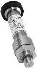 Pressure: Measurement by external digital sensor
| Range | 0-1 bar | 0-3 bar | 0-10 bar | 0-30 bar | 0-100 bar | 0-300 bar | 0-1000 bar |
| Absolute | X | X | X | X | X | X | X |
| Relative | X | X | X | X |
Available in relative, absolute and differential pressure. Connector: ¼ gas Resolution: 0.02% FS Accuracy: -0.05% FS from 10 to 40°C - 0.1% FS from -10 to +10°C and from 40 to 80°C This digital pressure module ACL433 is connected to CALYS 1500 through RS485 serial cable to the digital input connector. All data are digital. Measurements are compensated in temperature by a polynomial correction implemented into the firmware at factory.
Specifications and performances in process @23°C ±5°C
DC current: Measurement
With or without loop supply
| Range | Resolution | Accuracy / 1 year | Nota: Rin |
| 0-20 mA | 0.1 µA | 0.007% RDG + 0.8 µA | < 30 Ω |
| 4-20 mA | 0.1 µA | 0.007% RDG + 0.8 µA | < 30 Ω |
| ±100 mA | 0.1 µA | 0.007% RDG + 2 µA | < 30 Ω |
Temperature coefficient: < 7% of accuracy /°C beyond reference domain Loop supply: 24 V ±10% HART® compatibility: Input impedance Rin = 280 Ω CALYS 1500 also allows linear or quadratic signals to be linearized. Specifications given for CALYS configurations in: - Active mode (+24V ON) 1 Meter in passive mode (+24 V OFF) - Passive mode (+24 V OFF) 1 Meter in active mode (+24 V ON)
Direct voltage: Measurement
| Range | Full range | Resolution | Accuracy / 1 year | Nota: Rin |
| 100 mV | -10 mV to 100 mV | 1 µV | 0.005% RDG + 2 µV | > 10 MΩ |
| 1 V (1) | -100 mV to 1 V | 10 µV | 0.005% RDG + 8 µV | > 10 MΩ |
| 10 V | -1 V to 10 V | 100 µV | 0.007% RDG + 80 µV | = 1 MΩ |
| 50 V | -5 V to 50 V | 1 mV | 0.007% RDG + 0.5 mV | = 1 MΩ |
Temperature coefficient: < 5% of accuracy /°C beyond reference domain
Frequency and counting: Measurement
| Range | Full range | Resolution | Accuracy / 1 year |
| 10 KHz | 1 Hz to 10 KHz | 0.1 Hz | 0.005% RDG + 5 mHz |
| 100 KHz | 10 Hz to 100 KHz | 0.1 Hz | 0.005% RDG + 5 mHz |
Temperature coefficient: < 5 ppm/°C beyond reference domain Scale unit: Pulse / min and Hz Trigger level: 1 V Measurement on frequency signals or dry contacts Counting will be performed on defined time or infinite time
Resistance: Measurement
| Range | Resolution | Accuracy / 1 year |
| 400 Ω | 1 mΩ | 0.006% RDG + 8 mΩ |
| 3600 Ω | 10 mΩ | 0.006% RDG + 50 mΩ |
| 50 KΩ (1) | 100 mΩ | 0.008% RDG + 1 Ω |
(1) Range on channel 1 only. Temperature coefficient: < 7 ppm/°C beyond reference domain 2, 3 or 4 wires resistance measurement: automatic recognition of number of connected wires, with indication on screen Accuracies are given for 4-wire mounted probes Open circuit terminal voltage: < 10 V Continuity test: Open circuit for R > 1000 Ω and closed circuit for R < 1000 Ω
DC current: Emission
| Calibre | Résolution | Précision / 1 an | Note |
| 24 mA | 1 µA | 0,007% L + 0,8 µA | With or without loop supply (24 V) |
| 4-20 mA | 1 µA | 0,007% L + 0,8 µA | |
| 0-20 mA | 1 µA | 0,007% L + 0,8 µA |
Temperature coefficient: < 7 ppm/°C beyond reference domain Settling time: < 5 ms Specifications given for CALYS configurations in: - Active mode (+24V ON) 1 Meter in passive mode (+24 V OFF) - Passive mode (+24 V OFF) 1 Meter in active mode (+24 V ON) Pre-programmed steps
| 0% | 25% | 50% | 75% | 100% | |
| 4-20 mA linear | 4 | 8 | 12 | 16 | 20 |
| 0-20 mA linear | 0 | 5 | 10 | 15 | 20 |
| 4-20 mA quad | 4 | 5 | 8 | 13 | 20 |
| 0-20 mA quad | 0 | 1.25 | 5 | 11.25 | 20 |
| 4-20 mA valves | 3.8-4-4.2 | 12 | 19, 20, 21 |
Direct voltage: Emission
| Range | Full range | Resolution | Accuracy / 1 year | Minimum output load |
| 100 mV | -5 mV to 100 mV | 1 µV | 0.005% RDG + 2 µV | 1 KΩ |
| 1 V | -5 mV to 1 V | 10 µV | 0.005% RDG + 8 µV | 2 KΩ |
| 10 V | -100 mV to 10 V | 100 µV | 0.007% RDG + 80 µV | 4 KΩ |
| 50 V | -100 mV to 50 V | 1 mV | 0.007% RDG + 0.5 mV | 4 KΩ |
Temperature coefficient: < 5 ppm/°C beyond reference domain
Frequency and pulses: Emission
| Range | Resolution | Accuracy / 1 year |
| 1000 Hz | 0.01 Hz | 0.005% RDG + 5 mHz |
| 100 KHz | 1 Hz | 0.005% RDG + 5 mHz |
Temperature coefficient: < 5 ppm/°C beyond reference domain Scale unit: Pulse / min and Hz Pulse emission and dry contact simulation Max amplitude: 20 V selectable by user
Resistance: Emission
| Range | Full range | Resolution | Accuracy / 1 year | Notes |
| 400 Ω - 1 mA (Direct current) | 1 Ω to 400 Ω | 10 mΩ | 0.006% RDG + 20 mΩ | Iext : 0.1 mA - 1 mA |
| 400 Ω - 1 mA (Pulsed current) | 1 Ω to 400 Ω | 10 mΩ | 0.006% RDG + 30 mΩ | Iext : 0.1 mA - 1 mA |
| 400 Ω - 4 mA (Direct current) | 1 Ω to 400 Ω | 10 mΩ | 0.006% RDG + 20 mΩ | Iext : 1 mA - 4 mA |
| 400 Ω - 4 mA (Pulsed current) | 1 Ω to 400 Ω | 10 mΩ | 0.006% RDG + 30 mΩ | Iext : 1 mA - 4 mA |
| 3600 Ω (Direct current) | 10 Ω to 3600 Ω | 100 mΩ | 0.006% RDG + 100 mΩ | Iext : 0.1 / 1 mA |
| 3600 Ω (Pulsed current) | 10 Ω to 3600 Ω | 100 mΩ | 0.006% RDG + 200 mΩ | Iext : 0.1 / 1 mA |
Temperature coefficient: < 5 ppm/°C beyond reference domain Iext : Current received by the calibrator
Further functionalities
| File Menu | Users can save up to 10 full configurations of the instruments and recall them. Configurations include all programming done on instrument. |
| Scaling in measurement and simulation modes | Scaling allows process signals to be displayed in % of FS or in all other units. This function also allows sensors to be corrected after a calibration. |
| Relative measurement | The features allows the following :
|
| Simulation menu | Simulation value is set by entering value on keypad or by changing the specific digit with the cursor. |
| Square root | In current measurement and simulation, this function allows taking into account a quadratic signal coming from transmitter of type ΔP. |
| Statistical functions | Continuous display of average, minimum and maximum value of the signal under monitoring, as well as number of measurements. |
| Transmitter test | Transmitters can be verified using user procedures. 20 procedures can be stored as well as test results. Deviation curves are displayed. Edition of comprehensive test reports. |
| Switch test | In temperature or pressure mode, CALYS 1500 can control electronic thermostat and pressostat trigger levels. |
| Ramps generation | Starting, ending and length time values of simple or cyclic ramps can be set to do simulation. Number of ramps can also be adjusted in case of cyclic ramps for any signals. |
| Steps simulation | 2 modes are available:
In current simulation, user will have some additional preset values in function of range and according to 0%, 25%, 50%, 75% and 100% from selected gauge. Choice is done between gauges:
|
| Synthesizer | With 100 values manually set, CALYS 1500 enables users to draw a generation curve. |
| Transmitter function | CALYS 1500 is able to be used as a transmitter. Measurement input is copied on the output with scaling. |
| Memory capacity | Up to 10 full configurations (Input / output type, range…) 10,000 data into one or several measurement campaigns, i.e. more than one week work with configurations, measurements, calibration procedures and reports. |
General specifications
| Size (L x W x h) | 340 x 320 x 160 mm |
| Weight | 4.6 Kg |
| Display | 240 x 320 pixel liquid crystal graphical display with backlite & contrast control Display of result as table of values or trend curve |
| Power supply | 230 V ±10 %, 50/60 Hz |
| Battery | Type: Lithium-Ion Charging time: 3 hours Lifetime: 8 hours |
| Communication ports | USB |
Environmental specifications
| Reference range | 23°C ±5°C (HR : 45 to 75 % w/o condensing) |
| Operating reference range | -10 to 50°C (HR : 20 to 80 % w/o condensing) |
| Limit operating range | -15 to 55°C (HR : 10 to 80 % w/o condensing) (70% at 55°C) |
| Storage temperature limits | -30°C to +60°C |
| Maximum height | 0 to 2000 m |
| IP protection | IP54 according to EN 60529 |
Safety specifications
| Protections |
|
| Class | In accordance with EN 61010-1 |
| Rated voltage | 60 V |
| Chocks and vibrations | EN 61010-1 |
| EMC conformity | EN 61326-1, CEM 2004/108/CE |


