


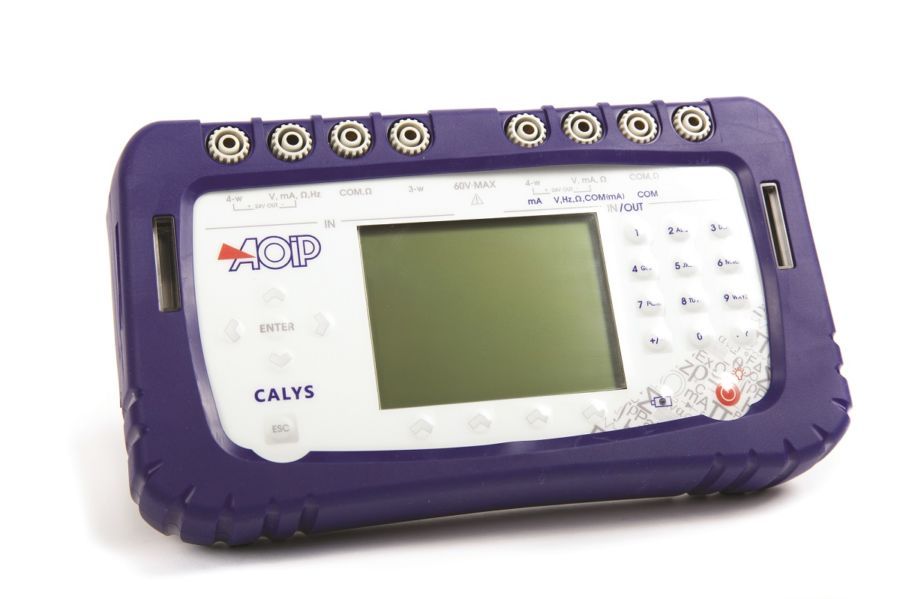
► Field multifunction calibrator for basic use
► CALYS 50 field multifunction calibrator is the perfect tool
for advanced process maintenance and use on test bench
in all industries.
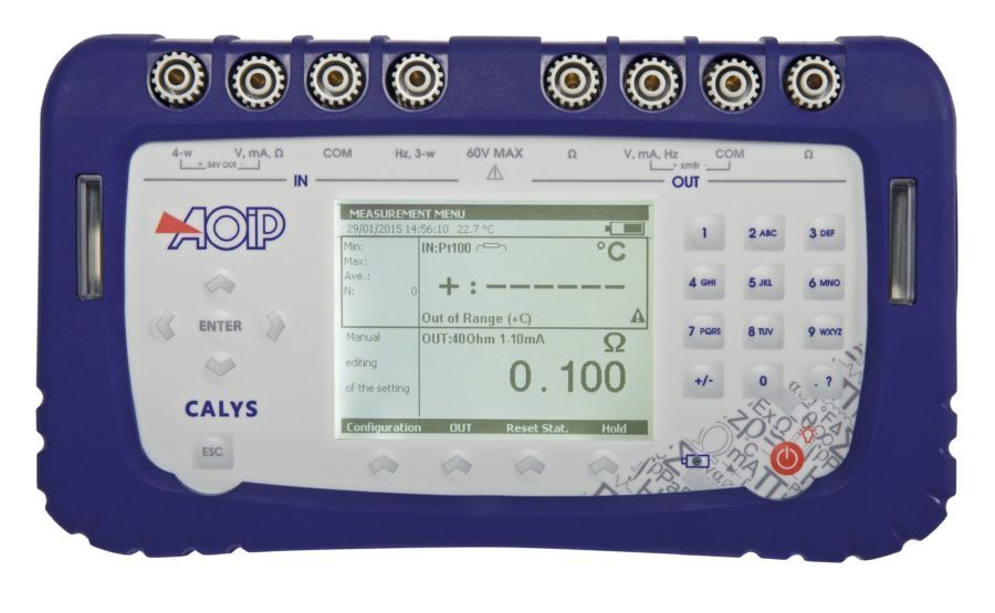
► Suitable for all field and lab measurements, it can simultaneously
measure and generate over two isolated channels various signals
of temperature, resistance, process and frequency
in one single instrument.
※ For industry and laboratory application only
CALYS 50 is a basic multifunction calibrator within CALYS range. It is the perfect tool for advanced process maintenance and use on test bench in all industries. Suitable for all field and lab measurements, it can simultaneously measure and generate over two isolated channels various signals of temperature, resistance, process and frequency in one single instrument.
It provides extended functionalities (temperature simulation, scaling, steps, synthesizer, statistical functions…), easily accessible through quick menus by function.
The instrument simultaneously measures and simulates:
Temperature: Up to 0,014% RDG
Resistance: Up to 0,012% RDG, 4 KΩ range
Current: Up to 0,0175% RDG, 50 mA range + 24 V loop supply
Voltage: Up to 0,013% RDG, 50 V IN / 20 V OUT range
Frequency: Up to 0,005% RDG, 20 KHz range (10 KHz in simulation)
IP 54, fully protected by an antichoc rubber holster, CALYS 50 integrates "easyconnect" terminals and a wide backlite display that makes it easy to use in any severe or dark conditions.
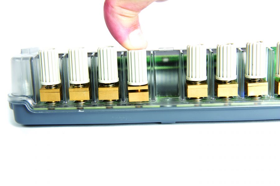
Easy connection system
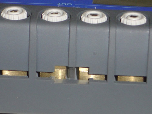
Connect your probes by simply pushing on the terminal top and insert wires of up to 3 mm or 10 AWG diameter and compensated thermocouple connectors.
Wires are held tight between two brass plates ensuring thermal stability and a very good cold junction compensation for thermocouples.
This system also enables 4 mm banana plugs and security connectors to be connected on the terminal top.
CALYS series, 4 models from basic use to advanced performances
| Specifications | CALYS 50 | CALYS 75 | CALYS 100 | CALYS 150 | |
| Top accuracy | 200 ppm | 130 ppm | 50 ppm | ||
| Temperature accuracy | Thermocouples (14) RTDs (12) |
0.013% RDG for Tc K 0.012% RDG |
0.01% RDG for Tc K 0.01% RDG |
0.005% RDG for Tc K 0.006% RDG |
|
| DC current + Loop supply 24 V |
Range Accuracy |
50 mA 0.0175% RDG |
100 mA 0.007% RDG |
||
| DC voltage | Range Accuracy |
50 V IN / 20 V OUT 0.013% RDG |
50 V 0.010% RDG |
50 V 0.005% RDG |
|
| Frequency | Range Accuracy |
20 KHz IN / 10 KHz OUT 0.005% RDG |
100 KHz 0.01% RDG |
||
| Resistance | Range Accuracy |
4000 Ω 0.012% RDG |
4000 Ω 0.010% RDG |
50 KΩ 0.006% RDG |
|
| Pressure | Range Accuracy |
Relative pressure: 30 bar / Absolute pressure: 1,000 bar 0.05% RDG |
|||
| Compliance to standards | 21 CFR Part 11 | ||||
| NADCAP Heat treatment AMS 2750 | |||||
| Additional functions | Advanced data exploitation: Scaling, relative measurement, simulation of ramps and steps, synthetizer, square root, statistical functions Transmitter function |
||||
| Additional functions | Switch test Calibration of transmitters |
||||
| Additional functions | Comparison calibration HART: Digital calibration and data transfer Calibration of thermistors |
||||
| Software | DATACAL calibration software for configuration and data management | ||||
| Memory | 10,000 data stored and recalled on screen as curve or list | ||||
Specifications and performances in temperature @23°C ±5°C
Uncertainty is given in % of reading (CALYS 50 display) + fixed value.
Resistive probes: Measurement and simulation
| Sensor | Range (Input and Output) | Resolution | Accuracy / 1 year (Measurement) | Accuracy / 1 year (Simulation) |
| Pt50 (α = 3851) | -220°C to +850°C | 0.01°C | 0.012% RDG + 0.06°C | 0.014% RDG + 0.18°C |
| Pt100 (α = 3851) | -220°C to +850°C | 0.01°C | 0.012% RDG + 0.05°C | 0.014% RDG + 0.12°C |
| Pt100 (α = 3916) | -200°C to +510°C | 0.01°C | 0.012% RDG + 0.05°C | 0.014% RDG + 0.12°C |
| Pt100 (α = 3926) | -210°C to +850°C | 0.01°C | 0.012% RDG + 0.05°C | 0.014% RDG + 0.12°C |
| Pt200 (α = 3851) | -220°C to +600°C | 0.01°C | 0.012% RDG + 0.12°C | 0.014% RDG + 0.33°C |
| Pt500 (α = 3851) | -220°C to +8500°C | 0.01°C | 0.012% RDG + 0.07°C | 0.014% RDG + 0.18°C |
| Pt1000 (α = 3851) | -220°C to +850°C | 0.01°C | 0.012% RDG + 0.05°C | 0.014% RDG + 0.08°C |
| Ni100 (α = 618) | -60°C to 180°C | 0.01°C | 0.012% RDG + 0.03°C | 0.014% RDG + 0.08°C |
| Ni120 (α = 672) | -40°C to +205°C | 0.01°C | 0.012% RDG + 0.03°C | 0.014% RDG + 0.08°C |
| Ni1000 (α = 618) | -60°C to +180°C | 0.01°C | 0.012% RDG + 0.03°C | 0.014% RDG + 0.08°C |
| Cu10 (α = 427) | -50°C à to 150°C | 0.01°C | 0.012% RDG + 0.18°C | 0.014% RDG + 0.1°C |
| Cu50 (α = 428) | -50°C to +150°C | 0.01°C | 0.012% RDG + 0.06°C | 0.014% RDG + 0.15°C |
Resistive probes measurements in 2, 3 or 4 wires: automatic recognition of number of connected wires, with indication on screen
Accuracies are given for 4-wire mounted probes
Take into account particular error of temperature sensor used and implementation conditions
Measuring current: 0.25 mA (Measurement) or from 0.1 to 1 mA (Emission)
Temperature coefficient: < 10% of accuracy /°C
Thermocouples: Measurement and simulation
| Type | Input range | Resolution | Accuracy / 1 year (Measurement) | Output range | Resolution | Accuracy / 1 year (Simulation) |
| K | -250 to -200°C -200 to -120°C -120 to +0°C 0°C to +1372°C |
0.2°C 0.1 0.05°C 0.05°C |
0.8°C 0.25°C 0.1°C 0.013% RDG + 0.08°C |
-240 to -50°C -50 to -0°C +0°C to +1372°C |
0.2°C 0.1 0.05°C |
0.6°C 0.1°C 0.013% RDG + 0.08°C |
| T | -250 to -200°C -200 to -120°C -120 to -50°C -50 to +400°C |
0.2°C 0.05°C 0.05°C 0.05°C |
0.7°C 0.25°C 0.1°C 0.013% RDG + 0.08°C |
-240 to -100°C -100 to -0°C +0 to +400°C |
0.2°C 0.05°C 0.05°C |
0.4°C 0.1°C 0.013% RDG + 0.08°C |
| J | -210 to -120°C -120 to +0°C +0 to +1200°C |
0.05°C 0.05°C 0.05°C |
0.25°C 0.09°C 0.013% RDG + 0.07°C |
-210 to -0°C +0 to +1200°C |
0.05°C 0.05°C |
0.2°C 0.013% RDG + 0.07°C |
| E | -250 to -200°C -200 to -100°C -100 to -0°C +0 to +1000°C |
0.1°C 0.05°C 0.05°C 0.05°C |
0.45°C 0.15°C 0.07°C 0.013% RDG + 0.05°C |
-240 to -100°C -100 to +40°C +40 to 1000°C |
0.1°C 0.1°C 0.05°C |
0.25°C 0.1°C 0.013% RDG + 0.05°C |
| R | -50 to +150°C +150 to +550°C +550 to 1768°C |
0.5°C 0.2°C 0.1°C |
0.8°C 0.013% RDG + 0.35°C 0.013% RDG + 0.2°C |
-50 to +350°C +350 to +900°C +900 to 1768°C |
0.5°C 0.2°C 0.1°C |
0.5°C 0.013% RDG + 0.35°C 0.013% RDG + 0.2°C |
| S | -50 to +150°C +150 to +550°C +550 to +1768°C |
0.5°C 0.2°C 0.1°C |
0.80°C 0.013% RDG + 0.35°C 0.013% RDG + 0.25°C |
-50 to +120°C +120 to +450°C +450 to +1768°C |
0.5°C 0.2°C 0.1°C |
0.8°C 0.013% RDG + 0.35°C 0.013% RDG + 0.25°C |
| B | +400 to +900°C +900 to +1820°C |
0.2°C 0.1°C |
0.013% RDG + 0.4°C 0.013% RDG + 0.2°C |
+400 to +850°C +850 to +1820°C |
0.2°C 0.1°C |
0.013% RDG + 0.4°C 0.013% RDG + 0.2°C |
| U | -200 to +660°C | 0.05°C | 0.15°C | -200 to +600°C | 0.05°C | 0.15°C |
| L | -200 to +900°C | 0.05°C | 0.2°C | -200 to +900°C | 0.05°C | 0.2°C |
| C | -20 to +900°C +900 to 2310°C |
0.1°C 0.1°C |
0.25°C 0.013% RDG + 0.15°C |
-20 to +900°C +900 to 2310°C |
0.1°C 0.1°C |
0.25°C 0.013% RDG + 0.15°C |
| N | -240 to -190°C -190 to -110°C -110 to +0°C +0 to +1300°C |
0.2°C 0.1°C 0.05°C 0.05°C |
0.5°C 0.15°C 0.08°C 0.013% RDG + 0.06°C |
-240 to -190°C -190 to -110°C -110 to +0°C +0 to +1300°C |
0.2°C 0.1°C 0.05°C 0.05°C |
0.3°C 0.15°C 0.08°C 0.015% RDG + 0.06°C |
| Platinum | -100 to +1400°C | 0.05°C | 0.3°C | -100 to +1400°C | 0.05°C | 0.3°C |
| Mo | +0 to +1375°C | 0.05°C | 0.013% RDG + 0.06°C | +0 to +1375°C | 0.05°C | 0.013% RDG + 0.06°C |
| NiMo/NiCo | -50 to +1410°C | 0.05°C | 0.013% RDG + 0.30°C | -50 to +1410°C | 0.05°C | 0.013% RDG + 0.3°C |
Thermocouples: D and G, for specifications, refer to the instruction manual (Available on request)
Accuracy is given for reference @ 0°C.
When using the internal reference junction (except couple B) add an additional uncertainty of 0.2 °C at 0 °C.
It is possible (thermocouple B excepted) to choose by programming the cold junction localization: External at 0°C, internal (temperature compensation of instrument’s terminals) or manually entered.
Temperature coefficient: <10% of accuracy /°C
Display unit: °C and F
Specifications and performances in process @23°C ±5°C
DC current: Measurement
With or without loop supply
| Range | Res. | Accuracy / 1an | Rin |
| 0-20 mA | 1 µA | 0.0175% RDG + 2 µA | < 25 Ω |
| 4-20 mA | 1 µA | 0.0175% RDG + 2 µA | < 25 Ω |
| ±50 mA | 1 µA | 0.0175% RDG + 2 µA | < 25 Ω |
Temperature coefficient: < 10 ppm/°C beyond reference domain
Loop supply: 24 V ±10%
HART® compatibility: Input impedance Rin = 280 Ω
Display with linear or quadratic scaling
DC voltage: Measurement
| Range | Res. | Accuracy / 1an | Rin |
| 100 mV | 1 µV | 0.013% RDG + 3 µV | > 10 MΩ |
| 1 V (1) | 10 µV | 0.013% RDG + 20 µV | > 10 MΩ |
| 10 V | 100 µV | 0.015% RDG + 200 µV | > 1 MΩ |
| 50 V | 1 mV | 0.015% RDG + 2 mV | > 1 MΩ |
Temperature coefficient < 7 ppm/°C beyond reference domain
(1) Specification domain: -0.8 V to +1 V
Frequency, counting: Measurement
| Range | Resolution | Accuracy / 1an |
| 20 kHz | 0.01 Hz | 0.005% RDG |
Temperature coefficient < 5 ppm/°C beyond reference domain
Scale unit: Pulse / min and Hz
Trigger level: 1 V
Measurement on frequency signals or dry contacts
Counting will be performed on defined time or infinite time.
Resistance: Measurement
| Range | Resolution | Accuracy / 1an |
| 400 Ω | 1 mΩ | 0.012% RDG + 10 mΩ |
| 400 Ω | 10 mΩ | 0.012% RDG + 100 mΩ |
Resistance measurement in 2, 3 or 4 wires: automatic recognition of number of connected wires, with indication on screen
Accuracies are given for 4-wire mounted probes
Temperature coefficient: < 7 ppm/°C beyond reference domain
Open circuit terminal voltage: < 10 V
Continuity test: Open circuit for R > 1000 Ω and closed circuit for R < 1000 Ω
Measurement current: 0.25 mA
DC current: Emission
With or without loop supply
| Range | Resolution | Accuracy / 1an |
| 24 mA | 1 µA | 0.0175% RDG + 2 µA |
| 4-20 mA | 1 µA | 0.0175% RDG + 2 µA |
| 0-20 mA | 1 µA | 0.0175% RDG + 2 µA |
Temperature Coefficient < 10 ppm/°C beyond reference domain
Settling time: < 5 ms
Specifications given for CALYS configurations in:
- Active mode (+24V ON) 1 Meter in passive mode (+24 V OFF)
- Passive mode (+24 V OFF) 1 Meter in active mode (+24 V ON)
Pre-programmed steps
0% 25% 50% 75% 100%
4-20 mA linear 4 8 12 16 20
0-20 mA linear 0 5 10 15 20
4-20 mA quad 4 5 8 13 20
0-20 mA quad 0 1.25 5 11,25 20
4-20 mA valves 3.8-4—4.2 12 19, 20, 21
DC voltage: Emission
| Range | Res. | Accuracy / 1an | Min load |
| 100 mV | 1 µV | 0.013% RDG + 3 µV | 1 kΩ |
| 2 V | 10 µV | 0.013% RDG + 20 µV | 2 kΩ |
| 20 V | 100 µV | 0.015% RDG + 200 µV | 4 kΩ |
Noise: 3 ppm (for 0.1 Hz to 10 Hz) and 5 ppm (for 10 Hz to 100 Hz)
Temperature coefficient: < 7 ppm/°C beyond reference domain
Settling time: < 5 ms
Frequency, pulse: Emission
| Range | Resolution | Accuracy / 1an |
| 1000 Hz | 0.01 Hz | 0.005% RDG |
| 10 kHz | 0.1 Hz | 0.005% RDG |
Temperature coefficient < 5 ppm/°C beyond reference domain
Resistance: Emission
| Range | Res. | Accuracy / 1an | Nota Iext |
| 40 Ω | 1 mΩ | 0.014% RDG + 3 mΩ 0.014% RDG + 10 mΩ |
10 mA 1 mA |
| 400 Ω | 10 mΩ | 0.014% RDG + 20 mΩ 0.014% RDG + 30 mΩ |
10 mA 1 mA |
| 4000 Ω | 100 mΩ | 0.014% RDG + 300 mΩ | 0.1 / 1 mA |
Temperature coefficient: < 5 ppm/°C beyond reference domain
Current establishing time: < 1 ms
Iext: Current received by the calibrator
Further features
| Scaling in measurement and simulation modes | Scaling allows process signals to be displayed in % of FS or in all other units. This function also allows sensors to be corrected after a calibration. |
| Relative measurement | The features allows the following :
|
| Simulation menu | Simulation value is set by entering value on keypad or by changing the specific digit with the cursor. |
| Square root | In current measurement and simulation, this function allows taking into account a quadratic signal coming from transmitter of type ΔP. |
| Statistical functions | Continuous display of average, minimum and maximum value of the signal under monitoring, as well as number of measurements. |
| Ramps generation | Starting, ending and length time values of simple or cyclic ramps can be set to do simulation. Number of ramps can also be adjusted in case of cyclic ramps for any signals. |
| Steps simulation | 2 modes are available:
In current simulation, user will have some additional preset values in function of range and according to 0%, 25%, 50%, 75% and 100% from selected gauge. Choice is done between gauges: |
| Synthesizer | With 100 values manually set, CALYS 50 enables users to draw a generation curve. |
| Transmitter function | CALYS 50 is able to be used as a transmitter. Measurement input is copied on the output with scaling. |
General specifications
| Size | 210 x 110 x 50 mm |
| Weight | 900 g |
| Display | 240 x 320 pixel liquid crystal graphical display with backlite and contrast control Display of result as table of values or trend curve |
| Power supply | 230 V ± 10 %, 50/60 Hz |
| Battery | Type: Lithium-ion Charging Time: 3 hours Lifetime: 8 hours |
| Communication ports | USB |
Environmental specifications
| Reference range | 23°C ± 5°C (RH: 45 to 75 % w/o condensing) |
| Operating reference range | -10 to 50°C (RH: 20 to 80 % w/o condensing) |
| Limit operating range | -15°C to +55°C (RH: 10 to 80 % w/o condensing) (70% at 55°C) |
| Storage temperature limits | -30°C to +60°C |
| Maximum height | 0 to 2000 m |
| IP protection | IP54 according to EN60529 |
Safety specifications
| Protections |
|
| Class | In accordance with EN 61010-1 Category II, pollution 2 |
| Rated voltage | 60 V |
| Chocks and vibrations | EN 61010-1 |
| EMC conformity | Immunity:
EN 61000-4-4
|


